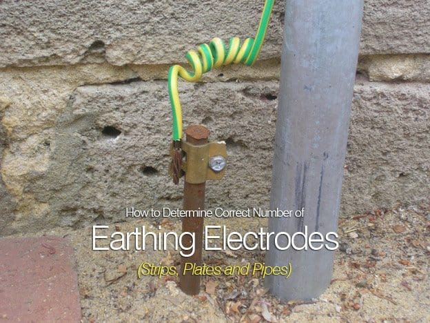

With additional measurements like the voltage, the test electrode moved 10% of the original voltage electrode to the earth system, separating it from the initial position and 10% closer than its original position. Therefore, it is crucial to measure the resistivity during the design of any earthing installations.Įarth resistance is the resistance of the ground electrode measured to perform a resistance check. The resistance of the earth electrode depends upon the resistivity of the soil in which the electrode is inserted. Four variables affect the earth resistance of a grounding system which includes: There are different earth resistance measurement methods used depending on the type of neutral system, the type of installation (residential, industrial, urban environment, rural environment, the possibility of cutting off the power supply. What are the methods of measuring Earth Resistance? There are different components included in an earthing system like earth electrodes, main earth terminals or bars, earthing conductors, protective conductors, equipotential bonding conductors, electrically independent earth electrodes (for measurements), termination fittings, bonding, welding kits and other materials. Earthing enables leakage current to flow away safely and is linked to an automatic cut off device (which ensures power supply). Various factors affect the earth resistance, like the composition of the soil, temperature, moisture content and depth of electrode. There are different materials used in the making, such as copper, aluminium, steel or galvanized iron. An earth electrode consists of a metal pipe or conducting plate connected to the earth. The purpose of earthing is to minimize the effect of transient voltage that occurred due to a strike of lightning.Įarthing connections are made by driving the earth electrode into several places. The Earth faults are hazardous and hence need proper earthing to prevent fault current from entering into anybody or metallic object.


 0 kommentar(er)
